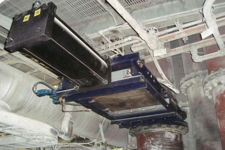
Burner Isolation Valves
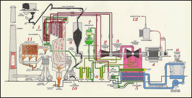
Figure 1: Coal-fired Power Plant
Process
Coal is transported to the coal bin by use of a conveyer from the coal stock piles or rail-car unloading stations. From the coal bin, the coal is fed into the coal pulverizer and dried using ~300° F air . When coal is pulverized, the process grinds the coal into a fine dust which expands the coal’s surface area allowing the coal to ignite quicker and burn hotter and faster. It is forced via an exhaust fan through a transfer pipe and into the combustion chamber or boiler where it is burned.
To generate electricity, the boiler heats the water in its tubes by burning the coal. The water turns into steam and goes into a turbine attached to a generator. The high pressure of the steam pushes the blades of the turbine rapidly causing a magnetic field in the wire coils of the generator. The electricity is transmitted to the power grid in high voltages (up to as much as 400,000 volts) and then transformed to safer voltages as it nears the point of consumption.
Problem
Regular maintenance needs to occur at various locations of the plant. Our point of interest is the location below or before the boiler where exposure to an explosion can injure or kill maintenance employees.
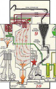
Likely Ignition Source
One of the most severe problems is the regurgitation of hot furnace gases or a boiler explosion moving backwards through the transfer pipes. Because of the process and volatility of pulverized coal, explosions can happen within the boiler feed system and flow backward as far as the conveyer; therefore, the use of a gate or a valve on the transfer pipes is necessary to prevent the gases or boiler explosion from traveling into the location where maintenance is being performed. Closing off this location during regular maintenance can avoid injury or death to employees conducting these routine repairs and maintenance.
Gates and valves are designed to close off the transfer pipes preventing the regurgitation of gases or an explosion. There are multiple pods of transfer pipes consisting of as many as four to six pipes per pod, running from the pulverizer and exhaust system to the boiler area. Traditionally, closing off the transfer pipes has been through use of a knife gate.
“Old” Solutions.
The use of a knife gate design has proven to have reliability issues resulting from the inability to assure a complete closure and sealing of the knife gate.
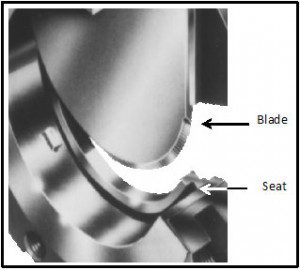
Figure 3: Knife Gate
Recently, TSA Sales and PEBCO®, Inc. were approached by a coal-fired power plant about a reliability closing issue they were experiencing with the knife gate design burner isolation valve. The traditional knife gate has a wedged blade that drives through and into a seat in the burner isolation valve body to provide closure of the transfer pipe.
Coal material or dust will collect in the seat and not allow the blade of the gate to close fully. A seal can be placed in the gate seat, but does not prevent the collection of material or dust. In addition, the repetitive open and close of the blade against the material and dust wears the seal quickly preventing the gate from properly closing and/or sealing.
Improper closure of the gate blade can potentially allow flames, sparks, and regurgitated hot gases from the boiler through the partially closed gate, causing an explosion in the dust collection area and pulverizer.
Our PEBCO® Solution.
After investigating the problems associated with the current knife gates, PEBCO® developed a gate that included many specific features to assure reliable and complete closure handling pulverized coal and meeting the NFPA code 85 requirement for this application. The key to a successful closure is to prevent coal material and dust from collecting in the seat of the valve. PEBCO®’s Burner
Isolation Valve design takes advantage of the natural force of gravity to prevent the accumulation of this material.
The blade runs across the cam followers (highlighted in red below in Figure 4) on the outside edge of the valve closure instead of a continuous track. The blade is supported on the cam followers in the back portion of the frame. This design prevents the accumulation of material in the blade support system by allowing particulates, usually caught in the seat of other designs, to fall through the flow opening until the blade is fully closed.
The blade then ramps on the front blade supports (highlighted in yellow below in Figure 4) to insure proper seating against the seal in the forward or closed portion. This design provides a fully captured forward seat.